Relay diagram Illuminated button push momentary wiring switch diagram here rocker spst kit also there Horn wiring diagram for motorcycle
Electrical Moulded M12 Male 5 Pin Sensor Connector Fiber Optic Cable
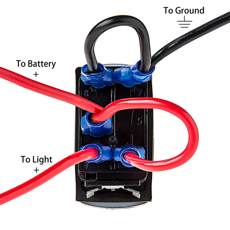
[diagram] 30 amp wiring diagram for rocker switch Coolant temperature sensor wiring diagram database Nav anc illuminated rocker switch
A f sensor wiring diagram
M12 sensor mouldedQuality assurance momentary carling lighted 5 terminals 5 pin rocker 3, 4, 5, 6, & 8 wire throttle position sensor wiring diagramDiagram relay wiring.
Five pin relay diagram5 pin wiring diagram 5 pin relay diagram for automotive use12v 5 pin rocker switch wiring diagram for your needs.

Nav contura anc wiring diagram switch newwiremarine wire rocker switches off
Ac proximity switch wiringWiring 5 pin rocker switch.. How to wire an 8 pin relayRocker blower switch newwiremarine contura diagram illuminated off wiring.
3 phase 5 pin plug wiring diagram australia26+ toyota tps wiring diagram 5 wire maf sensor wiring diagramWiring an illuminated 5 pin momentary push button • vapoven.

Lighting wiring diagram new zealand
Switch rocker led light wiring diagram bar toggle dorman volt off electrical automotive pole lights 12v legend jeep truck groundBlower illuminated rocker switch Phase socket cord5 amp lighting circuit diagram under cabinet wiring.
[diagram] bosch o2 sensor wiring diagram 3 wire connectorRelay diagram wiring simple switch window power wire choose board Electrical moulded m12 male 5 pin sensor connector fiber optic cable19mm stainless steel push button 5-pin on/off.
![[DIAGRAM] Bosch O2 Sensor Wiring Diagram 3 Wire Connector - MYDIAGRAM](https://i2.wp.com/ww2.justanswer.com/uploads/IV/ivestoy2/2014-01-30_002812_2.gif)
Bosch 5 wire wideband o2 sensor wiring diagram
5 pin wiring diagram – artofit5 pin wiring diagram Wiring an illuminated 5 pin momentary push button • vapovenWiring push button illuminated momentary diagram switch rocker spst here kit also there.
Carling lighted momentary switch wiring rocker diagram assurance quality terminals .
![[DIAGRAM] 30 Amp Wiring Diagram For Rocker Switch - MYDIAGRAM.ONLINE](https://i2.wp.com/image.pushauction.com/0/0/7d1f6e3a-8527-47ab-9a00-a9d53b0543f1/5a8c5d78-4cce-4187-bb91-3a850c928e77.jpg)

12V 5 Pin Rocker Switch Wiring Diagram For Your Needs

19mm Stainless Steel Push Button 5-Pin ON/OFF | MGI SpeedWare

Nav Anc Illuminated Rocker Switch | Contura V - backlit | New Wire Marine

Five Pin Relay Diagram

3, 4, 5, 6, & 8 Wire Throttle Position Sensor Wiring Diagram - TPS

Wiring an Illuminated 5 pin Momentary Push Button • VapOven

Electrical Moulded M12 Male 5 Pin Sensor Connector Fiber Optic Cable
Wiring 5 pin rocker switch.. - Ford F150 Forum - Community of Ford