Gm 6 pin throttle position sensor wiring diagram at francisco young blog Tps wiring sensor throttle position chevy location repair diagram 1990 ecm wire diagrams astro terminal body color 1995 engine changed 3, 4, 5, 6, & 8 wire throttle position sensor wiring diagram
THROTTLE POSITION SENSOR explanation for wiring diagram
Throtle body wiring diagram Accelerator pedal position sensor wiring diagram Chevy throttle body wiring diagram
Gm 6 pin throttle position sensor wiring diagram at francisco young blog
6 pin throttle position sensor wiring diagram throttle body positionThrottle position sensor problem? Wiring diagram throttle sensor position toyota control problem 2002 sienna electronic dbw bank pedal accelerator circuit 2005 ecu rx8club dtcFord throttle position sensor wiring diagram.
Pin wiring diagram ecu wiring ecu basic diagram bike any switches wireFord throttle position sensor wiring diagram Throttle position sensor explanation for wiring diagramCarburetor wiring diagram.

Sensor wiring pedal diagram accelerator position engine diesel app repair controls electronic guides module guide fig 1997
2014 chevy malibu electronic throttle body wiring diagram6 pin throttle position sensor wiring diagram 3, 4, 5, 6, & 8 wire throttle position sensor wiring diagram6 pin accelerator pedal position sensor wiring diagram.
26+ toyota tps wiring diagramUs shift technical support Understanding ford throttle position sensor wiring diagrams6 pin throttle position sensor wiring diagram.

Repair guides
Throttle position tps bosch connector webhelp maxxecu sensorsThrottle ford position gm sensor voltage color carb wires troubleshooting sensors codes e4od Throttle position sensor testing and explanationSensor throttle position diagram wiring explanation troubleshooting.
Throttle positionAccelerator pedal position sensor wiring diagram Maf sensor connector wiring diagram what pin do you check for 5 voltsWiring throttle wire drive haltech configuration allocated avi inputs recommended although required used if.

Throttle position sensors
Chevrolet throttle position sensor diagnosis and repair helpUnderstanding the wiring diagram for an 8 pin throttle position sensor The role of hall effect sensors in elevating throttle position sensors3, 4, 5, 6, & 8 wire throttle position sensor wiring diagram.
Drive by wire throttle wiringFord throttle position sensor wiring diagram How do you test a throttle body with a multimeter.


Gm 6 Pin Throttle Position Sensor Wiring Diagram at Francisco Young blog

How Do You Test A Throttle Body With A Multimeter

6 Pin Accelerator Pedal Position Sensor Wiring Diagram

Repair Guides

US Shift Technical Support

6 Pin Throttle Position Sensor Wiring Diagram
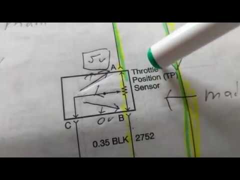
THROTTLE POSITION SENSOR explanation for wiring diagram

Understanding the Wiring Diagram for an 8 Pin Throttle Position Sensor